Three-dimensional impossible CAD
Recently I friend and I wrote a semi-serious paper called “The geometry of impossible objects” to be delivered at a mathematics technology conference. The reviewer was not hugely complimentary, saying that there was nothing new in the paper. Well, maybe not, but we had fun pulling together some information about impossible shapes and how to draw them.
You can see some of our programs hosted at repl.it.
But my interest here is to look at the three-dimensional versions of such objects; how to use a programmable CAD to create 3d objects which, from a particular perspective, look impossible.
Here’s an example in Perth, Western Australia:
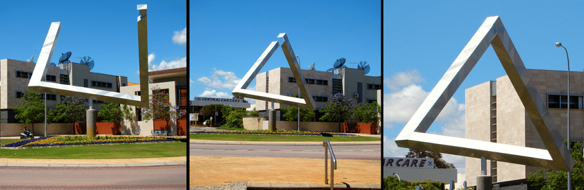
(I think the sides are a bit too thin to give a proper feeling for the shape, though.)
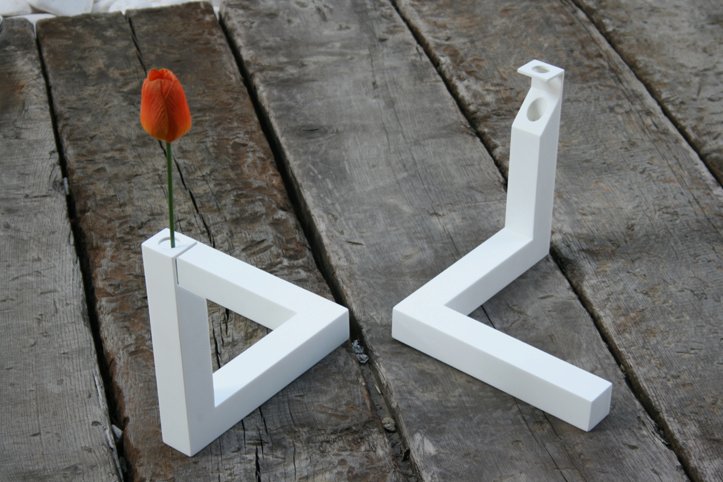
Another image, neatly showing how such a Penrose triangle can be created, is this of a “Unique vase”:
With this in mind, we can easily create such a shape in any 3D CAD program we like. I’ve spoken before about programmable CAD but then using OpenJSCAD. However, I decided to switch to Python’s CADquery, because it offered the option of orthographic viewing instead of just perspective viewing. This meant that all objects retained their size even if further away from the viewpoint, which made cutting out from the foreground objects much easier.
For making shapes available online, the best solution I found was the online and free viewer and widget provided by LAI4D and its online Laboratory. This provides not only a nice environment to explore 3D shapes, but the facility to export the shape as an html widget for viewing in an iframe.
Penrose triangle
In fact, this first shape is created with OpenJSCAD which I was using before discovering Cadquery. The only problem with OpenJSCAD - of which there’s a new version called simply JSCAD - is that it doesn’t seem to allow orthographic viewing. This is preferable to perspective viewing for impossible figures, as it’s much easier to work out how to line everything up as necessary.
You can see the version of my OpenJSCAD Penrose triangle by opening up up this link:
This should open up OpenJSCAD with the shape in it. You should be able to move it around until you get the impossible effect. You’ll see the JavaScript file that produced it on the right.
This shows the starting shape and what you should aim to produce:
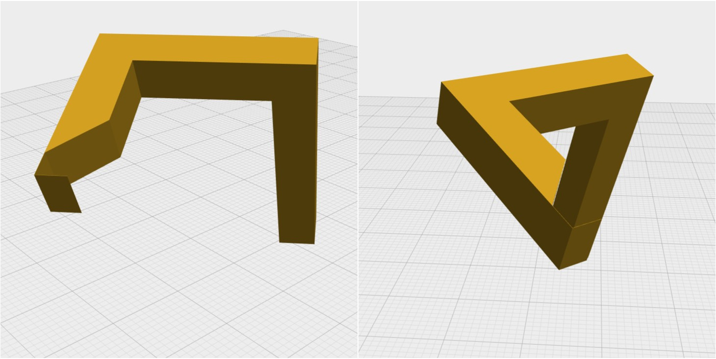
And here is the same construction in CadQuery, but working with an orthographic projection. As before, we create the cut-away beam as a two-dimensional shape given by the coordinates of its vertices, then “extrude” it perpendicular to its plane. The remaining beam is a rectangular box.
pts = [
    (0,0),
    (50,0),
    (50,10),
    (49.9,10),
    (49.9,0.1),
    (39.9,0.1),
    (30,10),
    (10,10),
    (10,40),
    (0,40)
]

L_shape = cq.Workplane("front").polyline(pts).close().extrude(10)
upright = cq.Workplane("front").transformed(offset=(5,45,-15)).box(10,10,50)

pt = Assembly(
[
    Part(L_shape, "L shape"),
    Part(upright, "Upright"),
],
"Penrose triangle")

exportSTL(pt,\"penrose_triangle.stl\", linear_deflection=0.01, angular_deflection=0.1)

show(pt)
The saved STL file can then be imported into the LAI4D online widget, and saved as an iframe for viewing.
The Reutersvärd triangle, which is named for the Swedish graphics designer Oscar Reutersvärd seems to predate the Penrose tirangle, and is a thing of great beauty.
Anyway, to see it in LAI4d, go to:
There are many hundreds of clever and witty impossible figures at the Impossible Figure Library, which I strongly recommend you visit!
Penrose Staircase
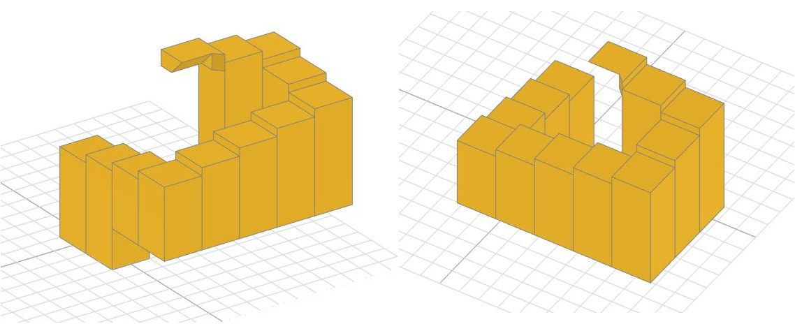
There’s a nice video on youtube here which I used as the basis for my model, but since then I’ve disovered other CAD models, for example on yeggi.com. Anyway, the model is made up of square prisms of different heights and bases, with a final shape jutting out at the top:
The Python code is :
{{< highlight python >}} transforms = [(0,0,0),(0,-1,0),(0,-2,5),(0,-3,5),(1,-3,5),(2,-3,5),(3,-3,5),(4,-3,5), (4,-2,5),(4,-1,5),(3,-1,5),(2,-1,20)] vscale = 0.2 vtransforms = [(t[0],t[1],t[2]*vscale) for t in transforms]
heights = [11,12,8,9,10,11,12,13,14,15,16,2]
boxes = [cq.Workplane(“front).transformed(\ offset = vtransforms[i]).box(1,1,heights[i]*vscale,centered=(True,True,False)) for i in range(11)]\n”,
pts1 = [(0,0),(0,1),(-1,1),(-1,0.2),(-0.2,0.2)] box12 = cq.Workplane(“front”).polyline(pts1).close().extrude(0.4)
pts2 = [(0.2,0),(0.6,0),(0.2,0.4)] prism = cq.Workplane(“YZ”).transformed(offset=(0,0,-1)).polyline(pts2).close().extrude(0.8) shape = box12.cut(prism).translate((2.5,-1.5,4))
boxes += [shape]
ps = Assembly( [Part(boxes[i],“Box “+str(i),"#daa520”) for i in range(12)], “Penrose staircase”)
exportSTL(ps,\“penrose_staircase2.stl\”, linear_deflection=0.01, angular_deflection=0.1)
{{< /highlight >}}
Below is an iframe containing the LAI4D widget, it may take a few seconds to load, and you may need to refresh the page:
If you get the shape into a state from which you can’t get the stair affect working, click on the little circular arrows in the bottom left, which will reset the object to its initial orientation.
Impossible box
This was just a matter of creating the edges, finding a nice view, and using some trial and error to slice through the front most beams so that it seemed that hhe read beams were at the front.
Here is another widget, again you may have to wait for it to load.